ESP32 Tutorial for Beginners: Getting Started
The ESP32 is a powerful, low-cost microcontroller that’s perfect for robotics, IoT projects, and DIY electronics. Developed by Espressif Systems, it features dual-core processing, built-in Wi-Fi, Bluetooth, and a variety of GPIO pins. Whether you’re building a smart robot or a home automation system, this beginner’s guide will walk you through the basics of the ESP32, its setup, and a simple project idea.
What Is the ESP32?
The ESP32 is an upgrade from the popular ESP8266, offering more processing power and connectivity options. It’s widely used because it’s affordable (around $5–$10) and versatile. With 34 GPIO pins, it can connect to sensors, motors, LEDs, and more, making it a favorite for robotics enthusiasts.
Materials You’ll Need
- ESP32 Development Board (e.g., ESP32-WROOM-32)
- USB Cable (Micro-USB for most boards)
- Computer with Arduino IDE installed
- LED and 220-ohm resistor (for a test project)
- Breadboard and jumper wires
Step 1: Set Up the Arduino IDE
To program the ESP32, you’ll use the Arduino IDE, a free software tool. Follow these steps:
- Download and install the Arduino IDE from arduino.cc.
- Open the IDE, go to File > Preferences, and add this URL to the “Additional Boards Manager URLs”:
https://dl.espressif.com/dl/package_esp32_index.json. - Go to Tools > Board > Boards Manager, search for “ESP32,” and install the package by Espressif.
- Select your board (e.g., “ESP32 Dev Module”) under Tools > Board.
Step 2: Test with a Simple LED Blink
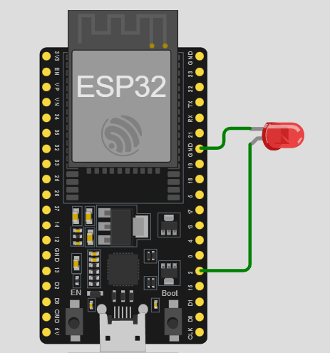
Let’s create a basic project to blink an LED. Connect the LED’s anode (long leg) to GPIO 2 of the ESP32 via a 220-ohm resistor, and the cathode (short leg) to GND. Then, upload this code:
void setup() {
  pinMode(2, OUTPUT); // GPIO 2 as output
}

void loop() {
  digitalWrite(2, HIGH); // LED on
  delay(1000);          // Wait 1 second
  digitalWrite(2, LOW);  // LED off
  delay(1000);          // Wait 1 second
}
Plug your ESP32 into your computer via USB, select the port under Tools > Port, and click “Upload.” The LED should start blinking!
ESP32 Pinout Diagram
Below is a simplified diagram of the ESP32. It shows the board with key pins like VCC (power) and GND (ground). In a real project, you’d refer to the full pinout for specific GPIO assignments.
Why Use the ESP32?
The ESP32’s Wi-Fi and Bluetooth capabilities make it ideal for wireless robotics projects. Imagine controlling a robot via your phone or sending sensor data to the cloud! It’s also beginner-friendly yet powerful enough for advanced applications.